
Introduction
The key challenge in smart irrigation is not whether to deploy sensors, but which sensor type to deploy at each point in the pipeline network. Main lines require wide measurement ranges with surge withstand capability; drip-irrigation branches demand micro-pressure sensitivity; and leak detection systems need long-term stability with low noise.
Agriculture accounts for approximately 70% of global freshwater withdrawals, yet traditional flood irrigation achieves water-use efficiency below 40%. Precision irrigation—which dynamically adjusts flow rates based on soil moisture, weather data, and real-time pipeline pressure—can raise efficiency above 80%. The foundation of precision irrigation is precision sensing, and the most fundamental, most widely deployed sensor in that sensing layer is the pressure sensor.
1. Three-Tier Pressure Monitoring Architecture
A typical agricultural irrigation network follows a tree topology: Water Source → Main Pipe → Branch Pipe → Drip / Sprinkler Endpoint. Each position places fundamentally different demands on the pressure sensor; using a single model across all locations is neither cost-effective nor technically sound.
Table 1: Three-Tier Pressure Monitoring Architecture
TierLocationTypical Pressure RangeKey RequirementDeployment QuantityL1 – Main PipePump discharge, trunk nodes0–600 kPaWide range, high overpressure tolerance, long service life1–2 per fieldL2 – Branch / ZoneIrrigation zone inlet0–200 kPaMid-range, weather-resistant, cost-sensitive1 per zone (30–80 total)L3 – Drip / Micro-sprayDrip tape, micro-sprinkler front end10–100 kPaHigh micro-pressure sensitivity, low power, compact footprintOptional; depends on precision level2. L1 – Main Pipe Pressure Monitoring
The main pipe directly receives the full discharge pressure of the pump. Water hammer—the pressure surge caused by sudden valve closure—can drive instantaneous pressure to 1.5–2 times the nominal value. The sensor must therefore provide adequate overpressure tolerance. Moreover, main-pipe sensor replacement is costly (potentially requiring system shutdown), placing a premium on long-term stability.
Selection guidelines:
• Select a pressure range 1.5–2× the rated working pressure to absorb water-hammer transients (e.g., for a 400 kPa system, choose 600–1000 kPa).
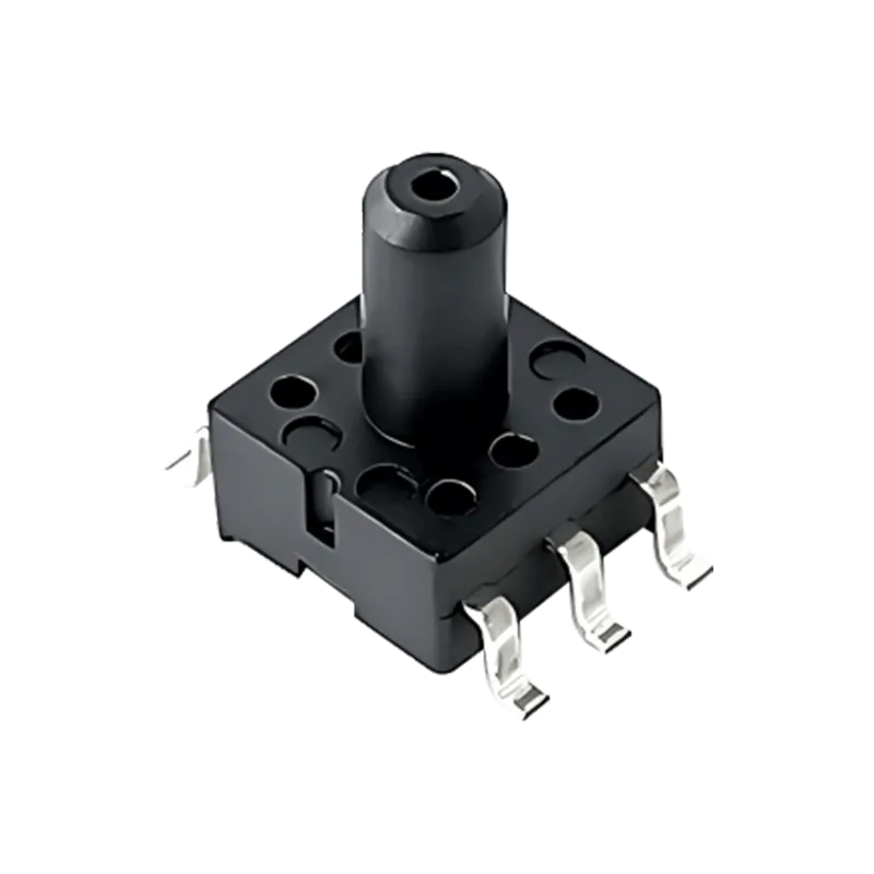
• Prefer DIP through-hole packages: in outdoor vault environments subject to vibration and wide temperature–humidity cycling, through-hole solder joints outperform surface-mount alternatives in long-term reliability.
Table 2: L1 Main Pipe Pressure Sensor Selection
ModelPackageRangeOutputExcitationSelection RationaleHBP411DIP6 through-hole100–1000 kPa gaugemV (ratiometric)≤ 15 VDC or ≤ 3 mADCThrough-hole soldering withstands outdoor vibration and thermal cycling; 4–6 kΩ bridge resistance with ultra-low power consumptionHBP451SOP8 SMD100–1000 kPa gaugemV (ratiometric)≤ 15 VDC or ≤ 3 mADCSOP8 footprint enables direct integration onto valve-controller PCBs; wide available range3. L2 – Branch / Zone Pressure Monitoring
Branch pressure monitoring accounts for the highest sensor count in any smart irrigation deployment. A 10-hectare farm may require 30–80 measurement points. The selection logic at this tier is straightforward: minimize BOM complexity. Any single component shortage, when multiplied across 80 channels, becomes a systemic supply-chain risk.
A key architectural choice deserves attention. A traditional mV-output sensor loop requires an external instrumentation amplifier and ADC, consuming 5–8 BOM line items per channel. An I²C digital-output sensor with on-chip ADC and temperature compensation collapses the local BOM to just 2–3 lines. At scale, the cumulative reduction in BOM line items runs into the hundreds—under component shortage conditions, the impact on supply-chain management far outweighs the sensor unit-price difference.
Decision flowchart:
• MCU has an available I²C bus → Choose HBP1101D (digital output; factory-calibrated; minimal BOM).
• MCU provides only ADC channels, or extreme cost pressure → Choose HBP401 (mV output; most economical).
• Need a middle ground: analog voltage output without an op-amp, avoid I²C driver development → Choose HBP1101A.
Table 3: L2 Branch Pipe Pressure Sensor Selection
ModelPackageRangeOutputSelection RationaleHBP401SOP6 SMD10 / 40 / 100 / 200 kPa gaugemV (ratiometric)Best cost-performance ratio; smallest footprint (7×7 mm); ideal for high-volume deployment; requires pressure isolation for liquid contactHBP1101DSOP6 SMD±100 to 1000 kPa gaugeI²C digitalOn-chip ADC with digital compensation; sensor local BOM reduced to 2 lines; factory-calibratedHBP1101ASOP6 SMD±100 to 1000 kPa gauge0.5–4.5 V analogRatiometric voltage output eliminates external amplifier; MCU ADC can read directly; wide supply voltage range4. L3 – Drip / Micro-Spray Endpoint Monitoring
Drip and micro-spray systems operate at 10–100 kPa. At these pressure levels, the sensor must deliver sufficient sensitivity and resolution: a 10 kPa full-scale range requires stable output at the sub-0.1 kPa level, placing stringent demands on MEMS die design and packaging stress control.
Endpoint sensors are typically battery-powered (solar panel + Li-ion), making input voltage range and standby current critical—parameters that are frequently overlooked during initial specification. Wide-input capability (2.7–5.5 V) allows direct battery connection without a boost regulator, simplifying the power tree and eliminating a potential failure point.
Table 4: L3 Drip / Micro-Spray Endpoint Sensor Selection
ModelPackageRangeOutputSelection RationaleHBP461SOP6 SMD1–200 kPa gaugemV (ratiometric)Range extends down to 1 kPa for high micro-pressure sensitivity; SOP6 compact package ideal for drip endpoint installationHBP1101DSOP6 SMD±100 kPa (custom 10 kPa available)I²C digitalCustom range on request; digital output reduces external component count; 2.7–5.5 V supply supports direct battery power5. Pipeline Leak Detection: Absolute vs. Differential Methods
Pipeline leak detection is among the highest-value applications for irrigation sensors. A single undetected pipe rupture can waste thousands of liters of water and cause crop loss. At the sensor level, two mainstream methods exist:
Method 1 – Absolute Pressure (Simpler)
Deploy a gauge pressure sensor at each end of the pipe segment. Monitor the trend of the pressure difference between the two measurement points. No external reference pressure is required, and deployment is straightforward. Recommended models: HBP401 or HBP1101 series—one sensor at each end keeps costs manageable.
Method 2 – Differential Pressure (More Sensitive)
Use a single differential pressure sensor to directly measure the pressure drop between the upstream and downstream ports. Minute leakage-induced pressure differences (typically at the hectopascal level) are captured directly by the differential sensor, offering higher sensitivity than the absolute pressure method. Recommended model: HBP5003 series (±500 Pa–200 kPa differential, SOP-16, I²C digital output).
Selection recommendation:
• Most agricultural scenarios → Absolute pressure method (dual gauge sensors). Lower cost, simpler deployment, easier maintenance.
• High-value crops or zero-tolerance leakage environments (e.g., greenhouse drip irrigation) → Differential method. The sensitivity gain justifies the additional deployment cost.
6. Media Compatibility: A Non-Negotiable Prerequisite
Before proceeding to outdoor deployment considerations, one engineering constraint must be addressed: most of the basic pressure sensors recommended in this article (HBP401 / HBP411 / HBP451 / HBP1101 / HBP461) are specified in their standard datasheets for non-corrosive, dry gases only—they must not directly contact water. Two workable paths exist:
Path A – Use Liquid-Compatible Models
The following HBGK models ship from the factory with liquid-contact capability: HBP421 / HBP422 (SOP8, non-conductive liquids), HBP431 / HBP432 (SOP8, pre-filled silicone gel for waterproofing), and the HBP1301 / HBP1302 / HBP1311 / HBP1312 series (SOP8, customizable waterproofing). For applications requiring direct contact with irrigation water, prioritize these models.
Path B – Pressure Isolation
Combine a basic gas-only sensor with a stainless-steel isolation diaphragm and silicone-oil pressure-transmission medium. The sensor die never contacts water; pressure is transferred through the diaphragm and oil. This approach is widely adopted in industrial pressure transmitters but adds per-unit material cost and assembly complexity.
Impact on earlier recommendations:
• If Path A is chosen, replace the L2 branch recommendation (HBP401 / HBP1101) with HBP431 / HBP432 (SOP8, pre-filled silicone gel, direct water contact).
• If Path B is chosen, the basic gas-only sensor selection remains unchanged, but the isolation diaphragm assembly cost must be included in the system BOM.
7. Outdoor Deployment: Environmental Protection & Temperature Drift
The greatest threat to an irrigation sensor is not the measured pressure itself, but the outdoor environment. Summer surface temperatures can exceed 60 °C; winter lows in northern regions can drop below −20 °C; and day–night swings of 20–30 °C are common. High humidity, condensation, and potential immersion demand basic waterproofing capability from every deployed sensor.
Beyond media compatibility, three additional parameters warrant close attention during sensor selection:
1. Temperature Compensation Range
Verify that the compensated temperature range covers the local annual extremes. The HBGK pressure sensor family offers a typical compensated range of −20 to +85 °C.
2. Waterproofing Options
Not all models are waterproof by default. Series marked "customizable waterproofing" (HBP431 / HBP432 / HBP1301 / HBP1302 / HBP1311 / HBP1312) can receive waterproof treatment at the factory. For models without native waterproofing, ingress protection must be addressed at the enclosure level.
3. Long-Term Drift
Irrigation sensors are typically deployed for years without replacement. Long-term stability (annual drift < 0.1% FS) matters far more in practice than factory accuracy (±1% FS). Factory accuracy can be corrected through system-level calibration; annual drift accumulates as an uncorrectable measurement error.
8. Selection Quick-Reference Table
Table 5: HBGK Smart Irrigation Pressure Sensor Quick-Reference Guide
Monitoring LocationRecommended ModelPackageRangeOutputKey Selection RationaleMain PipeHBP411DIP6100–1000 kPamVThrough-hole package for vibration resistance; high overpressure tolerance.Main Pipe (integrated valve)HBP451SOP8100–1000 kPamVSMD package for direct PCB integration on valve controllers.Branch (liquid-contact / IoT)HBP431 / HBP432SOP8100–1000 kPamVPre-filled silicone gel for waterproofing; direct water contact. HBP431 = gauge, HBP432 = differential.Branch (BOM-optimized)HBP1101DSOP6100–1000 kPaI²CDigital output with on-chip calibration; 2-line BOM; no external ADC required.Branch (analog voltage)HBP1101ASOP6100–1000 kPa0.5–4.5 VNo external amplifier needed; direct MCU ADC read; wide supply range.Drip Endpoint (micro-pressure)HBP461SOP61–200 kPamVRange extends down to 1 kPa for high micro-pressure sensitivity.Leak DetectionHBP5003SOP-16±500 Pa–200 kPamV / I²CDifferential sensor directly captures hectopascal-level leak signatures.Summary
Selecting pressure sensors for smart irrigation is not about finding the most expensive model—it is about matching the right sensor to each tier of the pipeline network. Main pipes demand overpressure tolerance and surge withstand capability. Branch pipes reward BOM simplification and supply-chain resilience. Drip endpoints demand micro-pressure sensitivity. Leak detection demands direct differential signal capture.
Plugging the seven models recommended above into your BOM gives you a fully justified selection at every network tier. Our engineering team stands ready to recommend optimal configurations for your specific application, or to customize sensors to your requirements.
About HBGK
Wuxi Haobang High-Tech Co., Ltd. (HBGK), founded in 2000, has specialized in MEMS sensor R&D and volume manufacturing for over 25 years. Our product portfolio spans pressure, flow, temperature, and current sensors. We operate an in-house MEMS wafer fabrication line and hold IATF 16949, ISO 9001, and ISO 14001 certifications.