Every high-voltage line strung across open country depends on a series of steel lattice structures doing a job most people never think about - holding conductors at the right height and tension, span after span, through wind, ice, and decades of weather. Power transmission tower design is the structural engineering work behind that, and getting it wrong has consequences reaching well beyond a single structure.
What Is Power Transmission Tower Design?
Transmission tower design engineers a steel lattice structure to carry conductors, earth wires, insulators, and hardware at specified heights and spans, while resisting wind, ice, and the mechanical loads the conductors impose. The tower isn't just holding dead weight - conductor tension, wind on the wire, and asymmetric loading during construction or a broken-wire event all factor into how the structure gets sized.
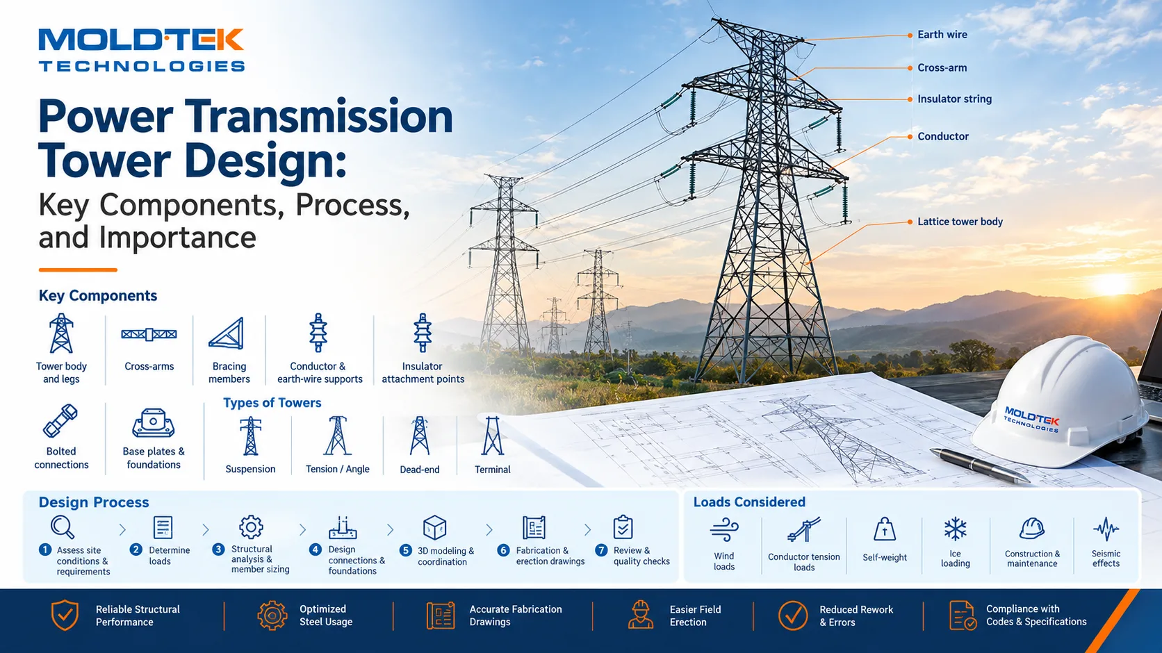
Key Components of a Transmission Tower
- Tower body and legs - the main lattice structure carrying loads to the foundation
- Cross-arms - support conductor attachment points at the correct spacing and clearance
- Bracing members - diagonal and horizontal members stabilizing the lattice
- Conductor and earth-wire supports - attachment points sized for line tension
- Insulator attachment points - connect insulator strings to the tower structure
- Bolted connections - joining lattice members with defined bolt patterns and grades
- Base plates and foundations - transferring tower loads into the ground
Types of Power Transmission Towers
- Suspension towers - support conductors in a straight line run
- Tension or angle towers - resist unbalanced pull where lines change direction
- Dead-end towers - anchor the line at a fixed termination point
- Terminal towers - connect the line into a substation
- Lattice steel towers - the common structural form for most of the above
Tower type depends on voltage level, line configuration, terrain, span length, and loading conditions specific to the route.
Power Transmission Tower Design Process
- Assess site conditions and project requirements
- Determine electrical and structural loading
- Run structural analysis and size members
- Design connections and foundations
- Build a 3D model and coordinate the structure
- Prepare fabrication and erection drawings
- Review the design and run quality checks
Loads Considered in Tower Design
- Wind loads on the structure and conductors
- Conductor and earth-wire tension loads
- Self-weight of the structure and attached hardware
- Ice loading, where applicable to the region
- Construction and maintenance loads
- Seismic effects, where required by the project location
Why Accurate Design and Detailing Matter
A transmission tower carries loads that don't forgive undersized members or misdetailed connections - a bolted joint sized incorrectly, or a bracing member left off a fabrication drawing, becomes a structural weak point in a structure meant to stand for decades in exposed conditions. Accurate member sizing, connection detailing, and foundation information keep fabrication and erection matched to the design, reducing the chance of field problems on structures that are expensive to access and correct once installed.
Benefits of Professional Transmission Tower Design
- Reliable structural performance under real wind, ice, and conductor loads
- Optimized steel usage for required capacity
- Accurate fabrication drawings matching design intent
- Easier field erection with fewer fit-up issues
- Reduced rework and fabrication errors
- Better compliance with specifications and applicable codes
Conclusion
Transmission towers work quietly and go unnoticed until something goes wrong, which is exactly why accurate structural design and detailing matter. Towers engineered correctly for their site conditions, loads, and connections keep power infrastructure reliable and durable across the long service life these structures are built for.